
Create hearts, splines and lettering with AI
Draw free closed outlines, join curves, create lettering and apply raised or engraved details to planar faces.
Updated:
Free shapes rather than part templates
A heart, curved pendant or handle outline can be built from freely chosen curve points. MCP tools do not prescribe a fixed heart recipe. Example: “Create a symmetrical heart plaque, about 80 mm wide and 4 mm thick. Add raised LOVE lettering to the front. Check the closed shape and image.”
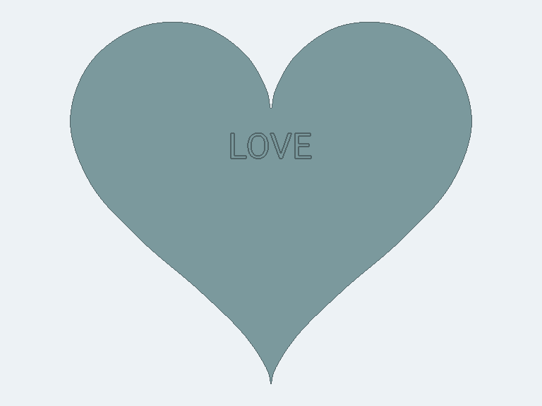
The illustration comes from an actual validated CAD body. Geometry checks and model views replace neither mechanical testing nor a print trial.
Existing spline capabilities
cad_create_sketch supports shape=spline with two to 64 fit points in one plane. With closed=true and at least three points it recognizes a closed outline. Extrude the source or a returned profileIds entry. The sketch and control points remain editable. Points are world coordinates in millimeters. By default the sketch lies in XZ with its normal along +Y. The curve interpolates fit points but can extend beyond their bounds between points. For exact external dimensions, AI must inspect actual body measurements and adjust the outline accordingly. Persisted fit points describe the editable spline. Closed regions and these modeling commands use the same bounded outline approximation as the sketch region builder. This does not promise an analytically exact spline edge throughout the modeling chain.
Why a spline can look faceted after extrusion
Previously each short sampled outline segment was extruded as a real planar wall face. A smooth spline could therefore acquire many narrow edges. New extrusion profiles derived from splines use a native curve fit in both CAD and MCP. Deviation from the saved region outline is checked in both directions; additional fitting tolerance is at most 0.01 mm. This is not a total accuracy guarantee against the original spline, since the region builder already approximates it. Pronounced corners split curve runs. In the validated heart, tip and notch remain exact corner endpoints. Deliberately polygonal sketches are not smoothed. Unsuitable or invalid fits use the previous outline. Mixed groups containing explicitly faceted source polygons may therefore remain faceted. A preview may still show sampled segments before native computation finishes.
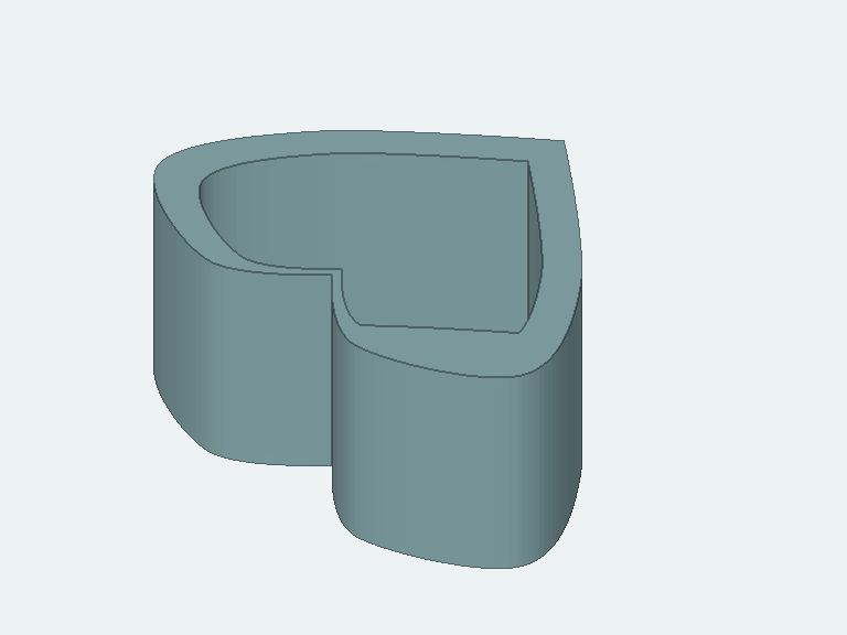
The actual test heart needs four native faces after fitting instead of 226. Cutting its interior creates an open heart container with curved inside and outside walls and a bottom. These counts describe this example. Existing saved extrusions are not rebuilt automatically; a new extrusion or deliberately committed linked-source edit uses the new construction. Continue checking solids and images after downstream features.
Tips, tangents and compound outlines
Optional fitTangents supplies one world vector per fit point. Direction and magnitude influence the curve; a zero vector allows a deliberate sharp point such as the heart tip or notch. Inconsistent, nonplanar or incorrectly counted tangents are rejected. For two open heart halves or outlines composed of several lines and curves, cad_join_sketches creates closed regions. Select sources explicitly. Endpoints must already meet; the tool neither bridges gaps nor draws missing sections. Sources remain and profileIds identifies the new regions.
Edit existing sketches
cad_get_sketch reads the current outline and a sketchToken. cad_update_sketch uses it to change dimensions of supported basic profiles or spline fit points, tangents and closed state. Read new profile IDs after changes. New extrusions retain a source link by default: editing the heart sketch regenerates its connected body after successful validation. Legacy or explicitly unlinked extrusions remain snapshots. See editing and detaching sketch links. Other bodies support the listed feature and parameter edits.
Text as actual geometry
cad_create_text creates outlines using the bundled Roboto font. Height is font size, not guaranteed visible cap height. Inner regions of B, O and similar letters remain holes. Disconnected letters return multiple profile IDs; they are not automatically united into one floating solid. The optional up direction controls upright lettering; in the default XZ plane, text reads along +X with its top towards -Z. Example: “Create SCREWS at an 8 mm font size as sketch outlines.” Extrude profiles individually or use cad_emboss_sketch to apply them together to a carrier. Characters available in the font are supported; arbitrary logos and additional font files are outside this tool's scope.
Raised lettering and engraving
cad_emboss_text applies text directly to a selected planar CAD face. Raised text uses operation=add and engraving uses operation=cut; depth is positive millimeters in both cases. A current topologyToken and actual faceId are required. The chosen center lies on the face plane; an optional up direction controls text orientation. AI must deliberately choose font size and placement rather than relying on automatic fitting. cad_emboss_sketch uses existing closed profiles at their actual position. Example: “Engrave this heart outline 0.5 mm into the flat top.” Profile and face must already be coplanar. Sources remain. Stale references, out-of-face outline points and invalid solids are rejected. These MCP emboss tools currently support planar targets. Cylindrical, spherical and freeform targets still require the interactive emboss workflow. Saved text emboss groups can be edited with cad_update_feature. Text and embossing in the CAD interface.
Test using ordinary requests
- “Create a closed heart outline as a spline and extrude it to 4 mm. Inspect the model in an image.”
- “Add raised LOVE lettering to the flat front, 0.8 mm high. Preserve all existing bodies.”
- “Show which dimensions and text on this body you can edit afterward. Do not change anything yet.”
Check shape, dimensions and connectivity separately. Calling a tool or describing an image correctly does not prove a functional or print-tested model. Check AI construction.