
Edit sketches and their linked solids
Regenerate extrusion, revolve, sweep and loft from retained source sketches and edit persistent feature dimensions in CAD and through AI.
Updated:
Connect an outline to its body
New normal Push/Pull extrusions retain their existing source sketch. The consumed outline is hidden rather than deleted. Editing the source regenerates the extrusion while keeping body and feature IDs. Subsequent features such as holes and hollowing replay their stored dimensions.
Step by step in CAD
- Draw a 40 × 30 mm rectangle and extrude it 8 mm high.
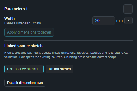
- Select the body and open the parameter panel. Under “Linked source sketch”, “Edit source sketch” opens the preserved outline.
- Change sketch width to 50 mm. Extrusion height remains 8 mm and placement is preserved. The change commits only after body validation succeeds.
- “Unlink sketch” keeps the current solid shape while preventing future outline edits from changing that extrusion step.
Regenerate revolve, sweep and loft
New revolves, sweeps and lofts also retain existing sketch sources. Create the body with the normal tool. Then select the body → Parameters → “Edit source sketch”. This reveals existing profiles and linked axis/path curves. Edit them with the normal sketch tools; the change commits after solid validation. - Revolve: edits to the wall section or selected straight sketch/construction axis regenerate the solid. The axis must remain in the profile plane. A saved angle row is preserved. - Sweep: the section and connected sketch curves remain linked, including spline paths. For example, increase a circular section from 4 to 5 mm diameter. Tight bends and self-intersections may fail; twist and circular patterns still require a straight open path. - Loft: ordered sections remain linked. For example, widen a handle’s middle elliptical section from 26 to 28 mm. Existing bores replay their stored dimensions. CAD can also retain links to selected sketch paths and guides; their endpoints must continue to match the sections.
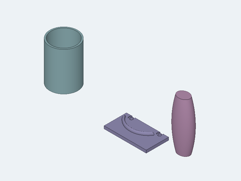
The actual test models show an open revolved vase with a bottom, a curved cable bracket with mounting plate and two stepped holes, and a smooth handle with an axial socket. Profile edits were validated after the downstream features. This verifies CAD geometry, not mechanical strength or print readiness.
Create persistent dimension rows
Click + in the parameter panel and choose “Feature dimension”. Select an existing feature or edge operation, then one of its offered dimensions. Name it “Extrusion depth”, “Wall thickness” or “Chamfer”. Registration first stores the existing value. Change the target and click Apply. Supported dimensions include suitable primitive sizes, extrusion heights, hole diameters and feature positions, hollowing, face offset, revolve angle and saved fillet/chamfer amounts. Angles use degrees; other dimensions use millimeters. Text embossing remains editable through its own editor and does not receive feature dimension rows here. This creates neither free-form equations nor automatic dependencies between arbitrary holes.
The same workflow through MCP
cad_get_history returns actual feature/edge IDs, current tokens, source links and saved rows. parameterizableParameters lists dimensions available for new rows. cad_add_parameter registers a normal CAD row; cad_set_parameters changes it. cad_update_feature and cad_update_edge_operation directly edit supported steps while the body is not managed by parameter rows. cad_extrude_sketch links new extrusions to their retained source by default. linked=false deliberately creates a snapshot. consume=true deletes the source and therefore creates no link either. cad_unlink_sketch detaches an existing link. Example: “Extrude this outline 8 mm high, register an Extrusion depth parameter and widen the source sketch to 50 mm. Verify the body and image.” cad_revolve_sketch, cad_sweep_sketch and cad_loft_sketches also default to linked=true. Use axisId for a linked revolve axis and pathIds for a linked sweep path. axisOrigin/axisDirection and path world points remain fixed inputs. MCP loft supports mode=ruled or smooth; guided variants are configured in normal CAD. cad_get_history separates profile, axis, path and guide source IDs. cad_unlink_sketch detaches all sources of the selected feature together.
Limits and existing projects
Legacy solids are not retroactively matched to sketches by similar shape. Selected model faces and edges remain snapshots. Outlines split into multiple regions or no longer closed may become ambiguous. Partially deleted source groups, locked bodies and unreplayable direct-edit histories are rejected; unlink first when needed. Sweeps here support a single closed section without holes; loft sections need matching hole counts. An invalid downstream feature rejects the whole outline edit and its body changes. Making a box smaller does not automatically move holes or reduce wall thickness. Deleting the complete source retains the last solid geometry and detaches its link. Existing independent pattern copies do not acquire an editable pattern count. Saving and loading preserve new links and rows; undo/redo restores the shared document snapshot. See Parameters and fixed references and MCP editing for further limits.