Dimension sketches and keep their relationships
Use the same dimensions and constraints in CAD and through MCP: fixed points, distances, angles, tangency and mirrored splines.
Updated:
From a drawing to an editable sketch
A distance between two circle centers expresses a different intent than two unrelated positions. A saved dimension keeps that distance editable. Geometric constraints preserve tangency or mirror a curve half. CAD and AI use the same sketch tools. A feature dimension row instead controls a solid operation such as extrusion height or wall thickness.
Example: two circles in normal CAD
- Draw two circles in the same plane. Fix the first circle center as the reference.
- Use the dimension tool to create a point-to-point dimension between their centers. Choose horizontal mode if needed and enter 30 mm.
- Click the saved dimension and change it to 35 mm. The first center stays fixed; the second follows the dimension.
- Switch an additional inspection dimension to “Reference”. It measures the existing geometry without changing it. Switch back to “driving” to control geometry again.
Sketch-plane dimensions do not automatically mean world X or Z. Horizontal and vertical refer to that plane, including rotated sketches. A locked object can serve as a read-only reference; driven geometry must be editable.
Example: a persistently symmetric heart
Draw two open spline halves and a straight centerline in the same plane. The halves must meet at the tip and notch. Lock the centerline as the reference. Choose “Symmetry” and pick the leading half, following half, then centerline. Changes to the leader mirror onto the follower. Create a horizontal point dimension from the axis center to an outer fit point of the leading half, for example 25 mm. Join both halves into a closed region and extrude it 3 mm. With its sketch link retained, the solid and outline follow later dimension edits together.
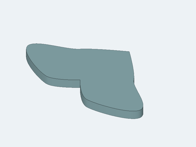
The actual test model has a 50 mm solid width after these steps. A general spline can overshoot between fit points: a 25 mm fit-point distance therefore does not guarantee 50 mm outer width for other curves. Check actual body bounds and the image. Symmetry connects two matching curves; it does not create self-symmetry on one closed spline.
The same workflow with AI
Example request: “Draw two circles, fix the first center and dimension their horizontal center distance to 30 mm. Then change the saved dimension to 35 mm. I want to edit these dimensions in CAD later.” cad_get_sketch_constraints reads actual point/rectangle-edge picks, plane axes, stored constraints and dimensions. A current constraintToken protects subsequent edits. Requery after every mutation; use nextOffset for longer components. AI must not invent IDs. - cad_apply_sketch_constraint applies a normal geometric relationship. Symmetry order is leader → follower → straight axis. Reapplying “Fix” keeps it fixed. - cad_add_sketch_dimension creates a persistent point, point-to-line, parallel line distance, angle or arc dimension. Values are absolute targets in millimeters or degrees. - cad_set_sketch_dimension edits a returned dimension. primary/secondary are intrinsic rulers scoped to the given sketch object; saved dimensions have their own IDs. Reference dimensions cannot take driving values. Splines use actual fit points rather than an invented width ruler. - cad_remove_sketch_constraint removes one returned relationship or saved dimension. object-lock explicitly unlocks the object. The current shape remains unless other conditions require adjustment. Dimensions also appear in normal CAD and survive saving/loading. Changes to linked source sketches validate affected solids before one shared commit. Independent sketch copies do not inherit foreign dimension or fix references.
Conflicts and limits
Saved dimensions may bind a spline fit point by index. While such index bindings remain, validated sketch edits reject a change in fit-point count: removing a middle point could otherwise make the same index refer to a different point. First remove affected bindings, edit the point count, then dimension the actual returned points again. Loaded indices outside the existing point list are reported as missing references; historical point identity cannot be recovered from old indices alone. When an existing or loaded model already contains incompatible sketch conditions, AI can use cad_get_sketch_constraints for read-only diagnosis. Per-source issues identify the actual constraintId and kind conflict, or reference for a missing point reference. Example: “Check the sketch constraints for conflicts without changing anything.” The check neither moves geometry nor removes bindings. An empty list does not prove full constraint. Do not fix both ends of a line and then request a different direction or length. Conflicting drafts are rejected. Remove the unwanted relationship explicitly or use a reference dimension. An impossible hollowing after a sketch shrink rejects the complete dimension and solid edit. When a saved dimension loses its reference line or point, diagnosis reports reference, including for measurement-only dimensions. An old stored value is not a valid measurement. Such records may exist without a visible dimension label. Use cad_remove_sketch_constraint with the reported ID to remove them individually without recreating the sketch. Other existing defects may remain during incremental cleanup; new conflicts and invalid downstream solids are still rejected. Recheck afterward and recreate valid dimensions as needed. This is neither a general equation editor nor a proof of full constraint. Relationships require compatible geometry and the correct pick order. Splines support paired symmetry, but not automatically every line/circle constraint. Continue checking closed regions, solid validity and images. See the tool reference, free curves and sketch links for more limits.